
Many of our products have the suffix “AC” behind the product name. This suffix is an indication that AC LED modules are installed in these products. In this technology, a significant part of a regular LED module is not required. The ballast.
How does it work?
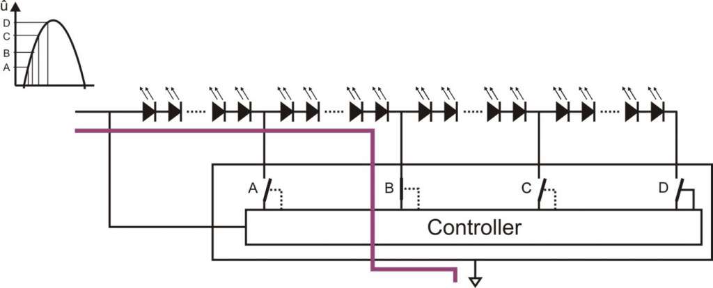
The following image explains the basic function of high-voltage LEDs. The circuit is operated directly on a rectified AC voltage. The LED chain – here a large number of individual LEDs or special COB modules can be used – is controlled with the help of the controller.

Depending on the current height of the sine half-wave, the controller switches the switches A-D and dynamically creates an LED chain, the total opening voltage of which is just below the current height of the half-wave. Since the number of channels is limited, this is done in segments.

In this example, the instantaneous value of the sine half-wave is still very low. Consequently, only a few segments are activated. The rest of the chain remains dark.
The next image shows the switches as they apply for state B:
Here, the number of illuminated LEDs is already larger.
The sequence can be continued until all LEDs are activated. It can be seen from this that the number of illuminated LEDs grows and decreases dynamically with the sine wave. The observer notices relatively little of this, as this process is hardly perceptible to the eye. They see a uniformly illuminated LED chain.
In the following image, the brightness curve, the current curve, and the mains voltage have been recorded:

For this measurement, a controller with six stages was used. The yellow curve shows the six jumps when the segments are switched on. The jumps are also visible in the current (green). The blue curve shows the course of the mains voltage. It is also noticeable that no light is emitted in the first period after the zero crossing, because the lower threshold must first be exceeded. For the human perception of brightness, this is unproblematic, and the EMC requirements (e.g., grid feedback) are also met.
The advantage
Lamps without electronic control gear require fewer components. This has several advantages. Costs are reduced, as large and expensive components are not needed, and the likelihood of failure is lower. This has another important advantage for the potential operating life: The electrolytic capacitors usually necessary in electronic control gear are completely missing here. Typical AC/DC converters achieve lifespans of around 15,000 hours, while this technology can indeed achieve 50,000 hours or more. It is therefore roughly in line with the expected lifespan of the LED. For the user, this is a twofold advantage: AC LED modules are very efficient, i.e., economical in energy consumption, and the entire system is designed for a very long service life. The replacement of control gear or light sources is therefore completely unnecessary. No maintenance costs arise from part replacement.
Another operating mode is built into the module automatically and without additional costs: The use of the modules in an emergency light. The module operates with supply voltages of 230V alternating or direct current. When supplied with direct current, the light output, power, and warming increase slightly.
Electromagnetic compatibility (EMC)
Several factors need to be considered when assessing EMC. What effort must be made to eliminate the inevitable interferences from microcontrollers, power converters, or other oscillating circuits? Here LED modules offer significant advantages: These circuit parts do not exist with this technology! Additionally, there are requirements for noise immunity, for example, burst and surge impulses. To ensure resistance to these conducted disturbances, a relatively small input stage equipped with only a few passive components is needed. These components protect the lamp from damage.
Where there is light, there is also shadow!
A small disadvantage must be accepted (if necessary): Since interference signals such as bursts are coupled onto the mains voltage, there can be slight flickering during their influence. An additional advantage lies in the low harmonic distortion (THD – Total Harmonic Distortions) of the current drawn (Image 6). This value is a measure of the nonlinear distortion of the current and is very low here.
AC LED modules and dimming
However, the dimming is not as clean and smooth as with direct current-operated LEDs with PWM or analog dimming. If the current flow angle is chosen very small and already turned off again during the rising curve, it may happen that the voltage is around one of the thresholds and the LEDs of this segment flicker. The more or less precise functioning of dimmers also affects flickering.